And The World Did Not Beat A Path To His Door

4,400 attempts at a solved problem

Overengineered

Deploying forty moving parts against an adversary that weighs less than a slice of bread.
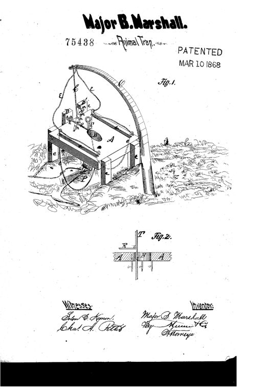
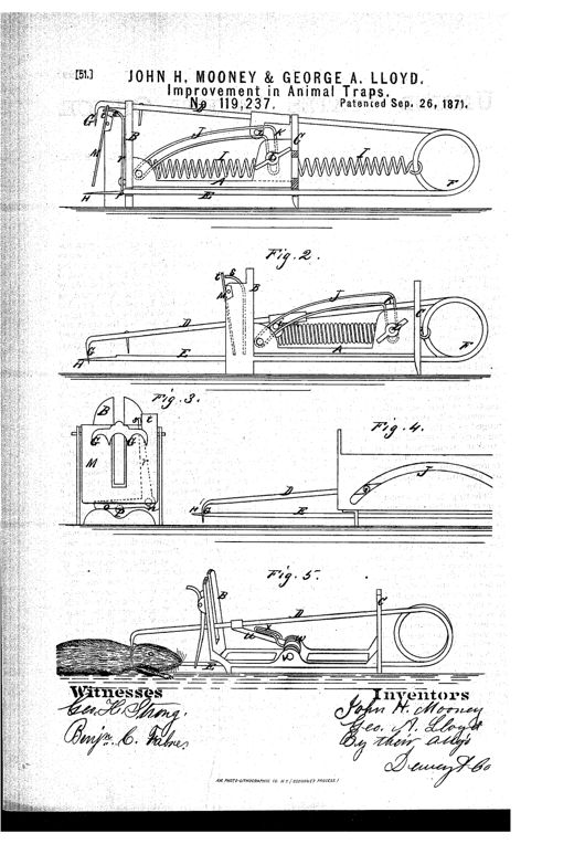
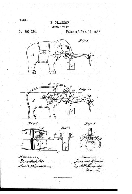
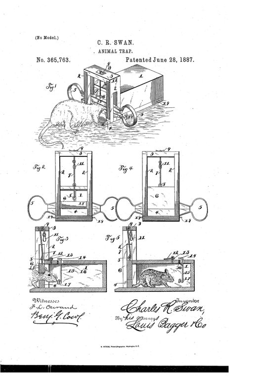
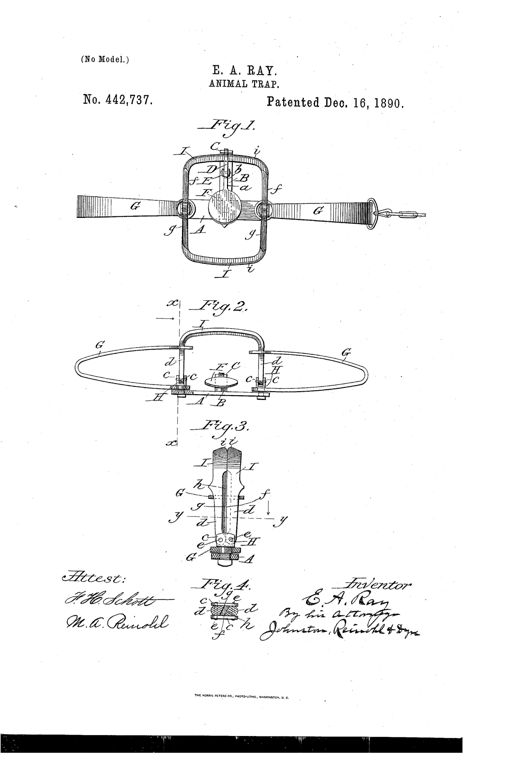
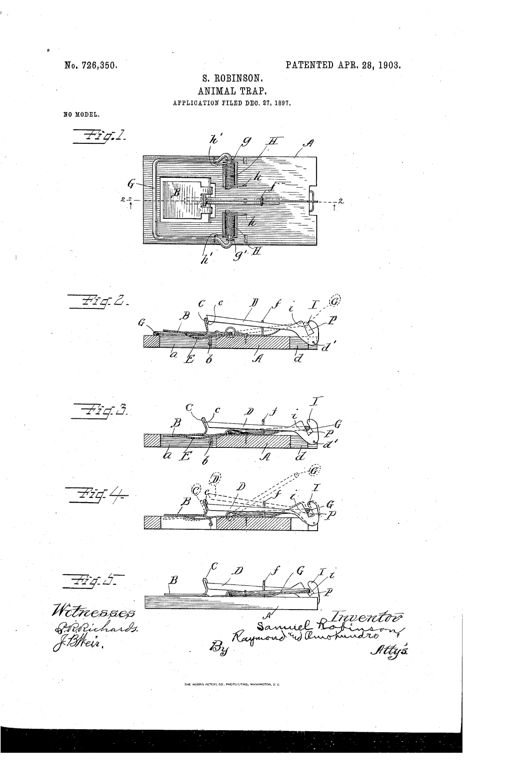
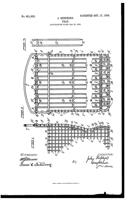
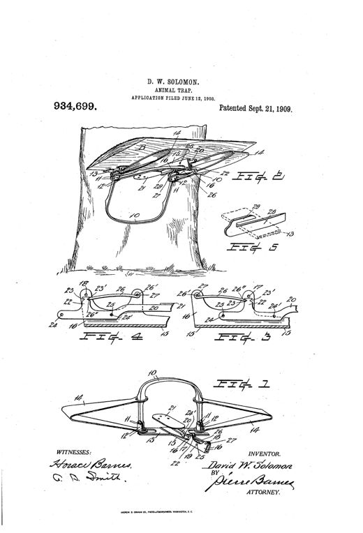
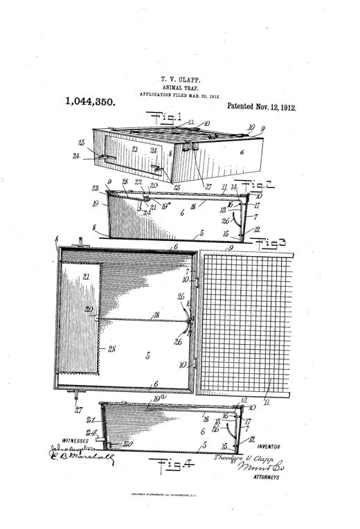
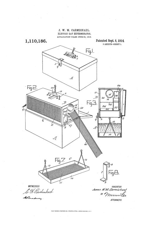
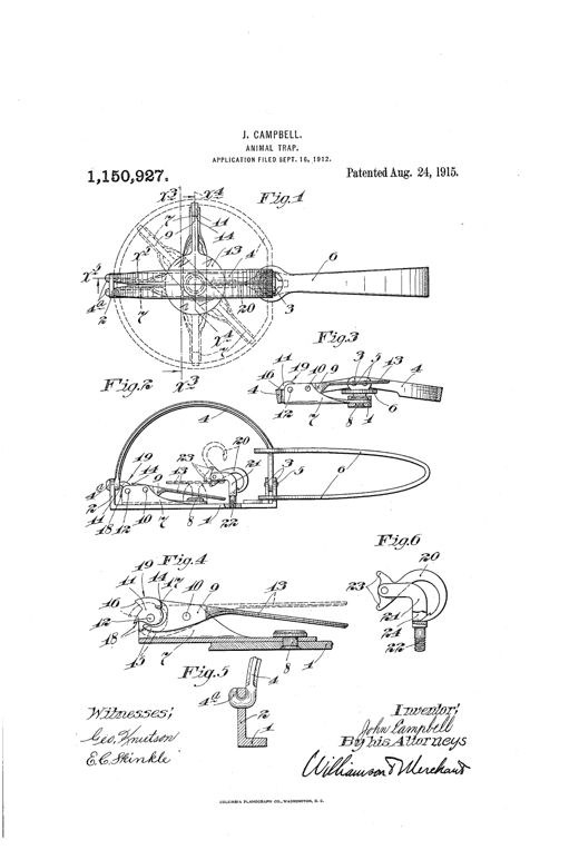
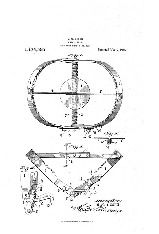
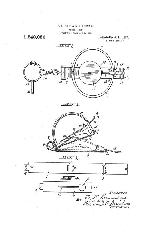
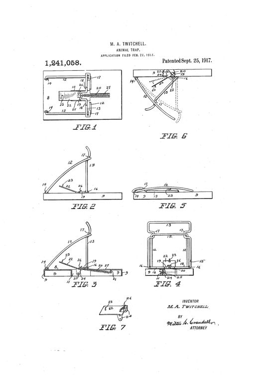
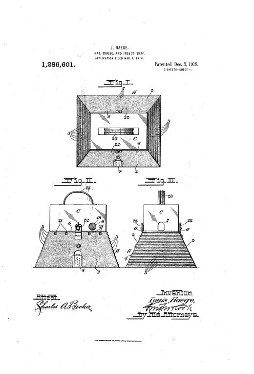
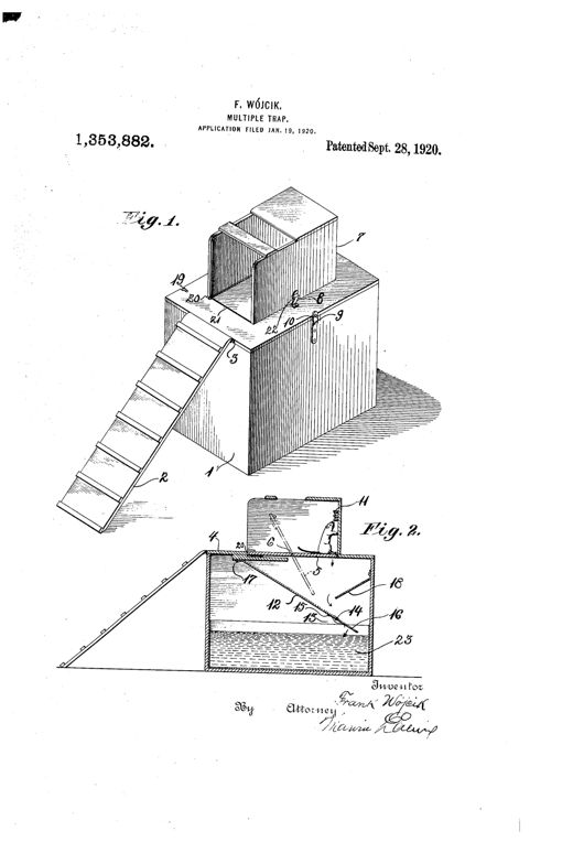
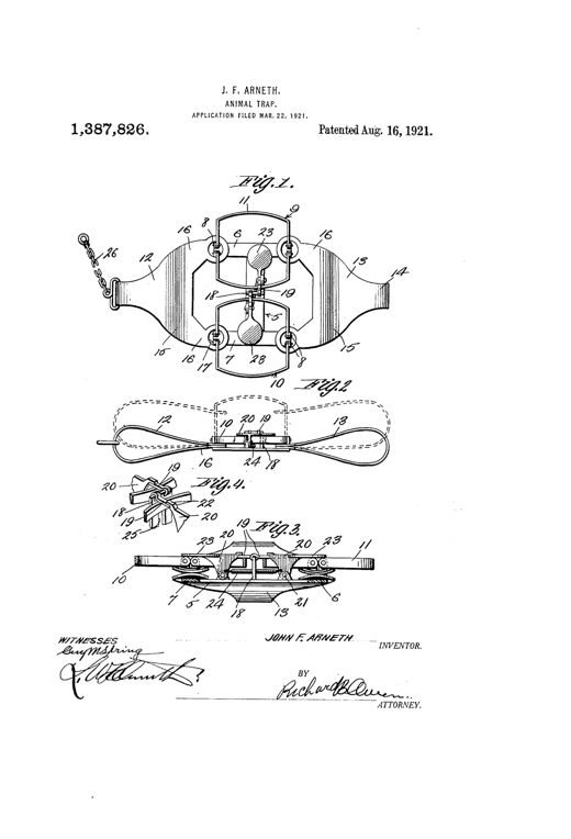
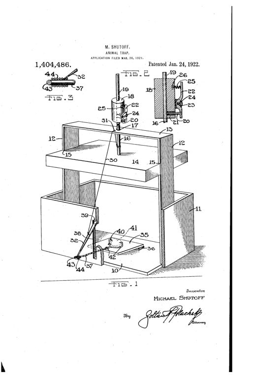
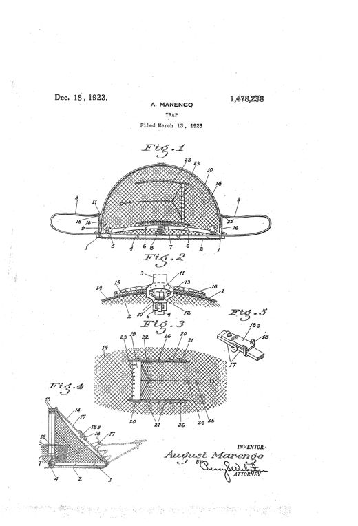
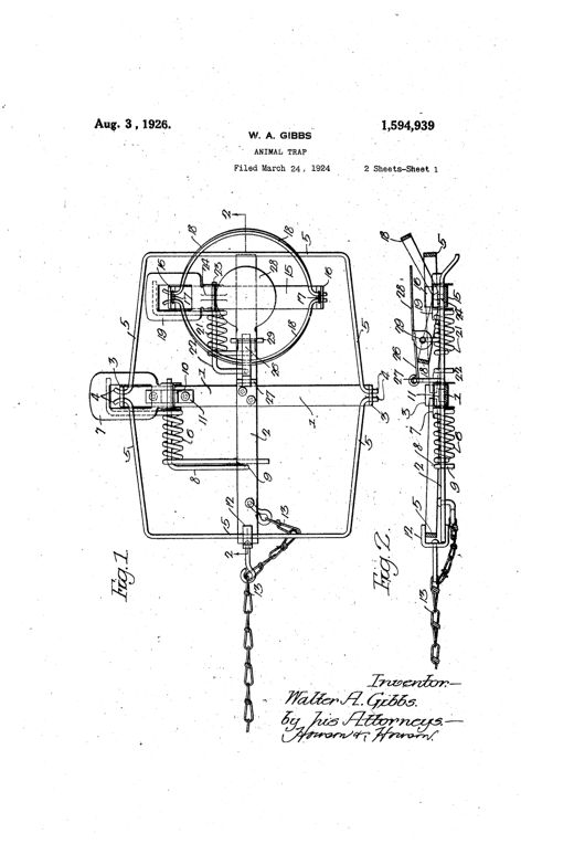
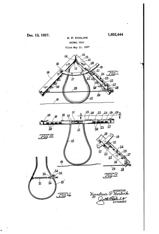
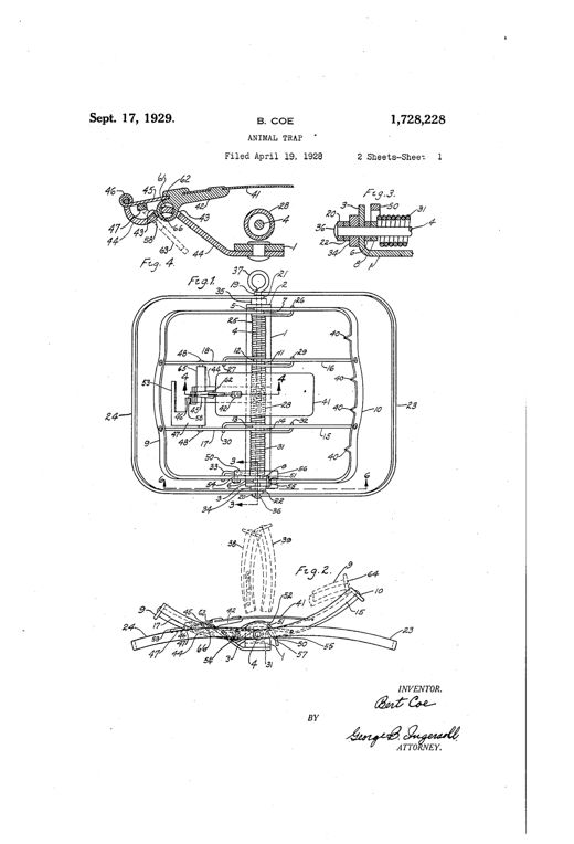
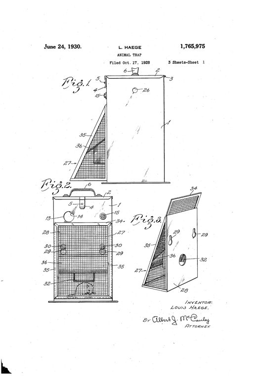
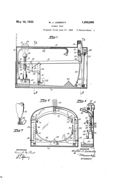
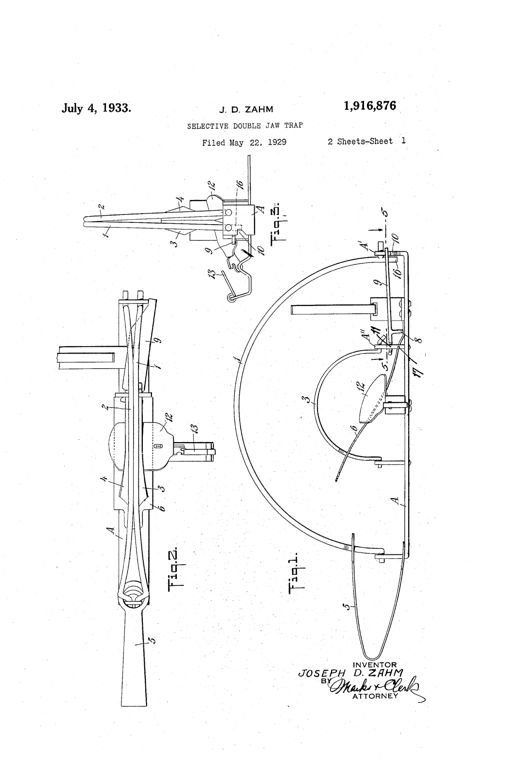
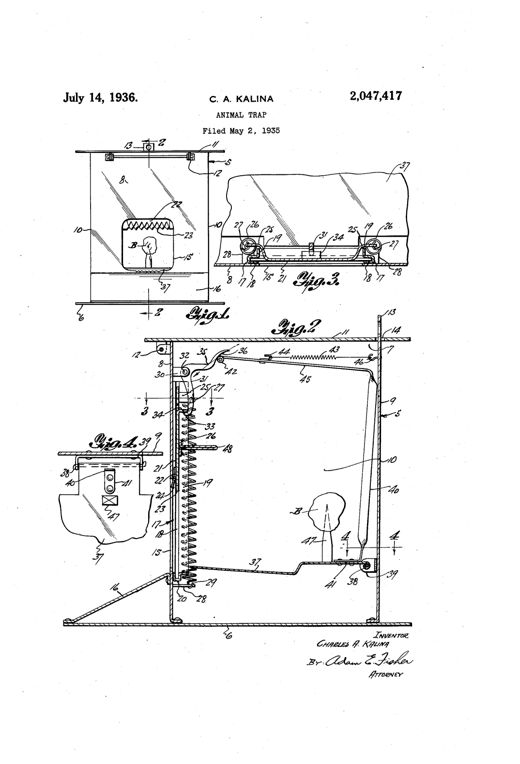
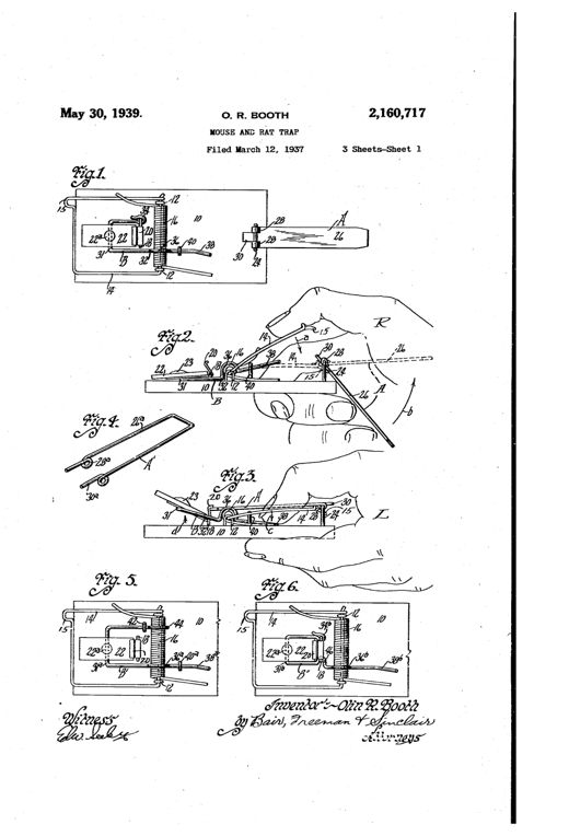
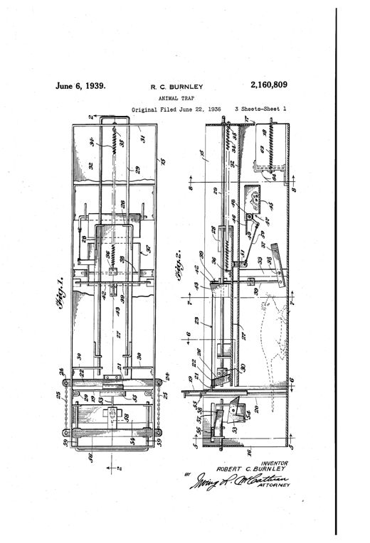
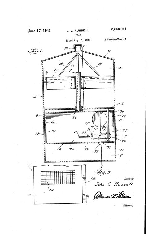
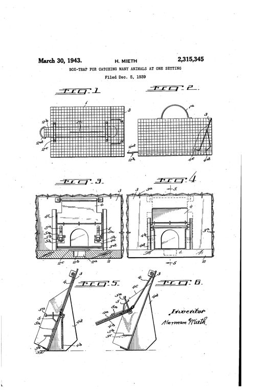
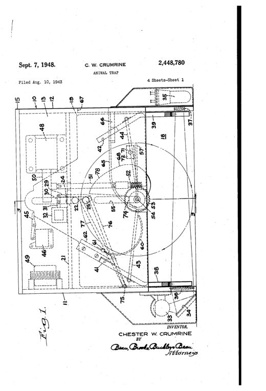
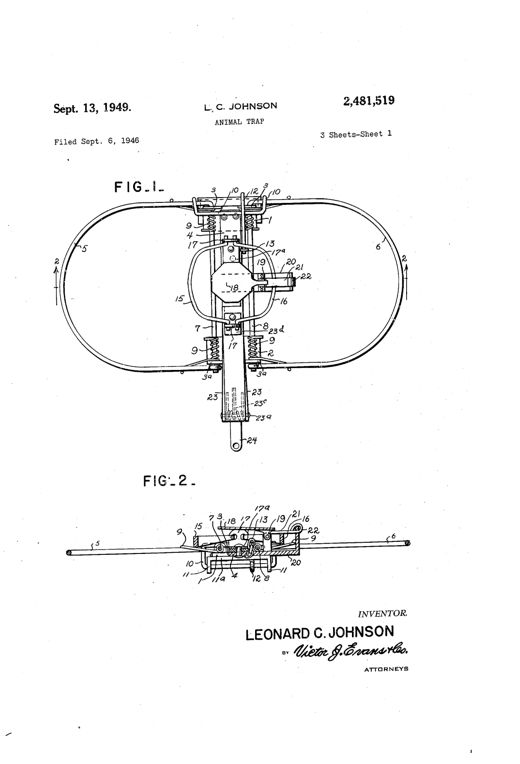
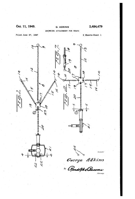
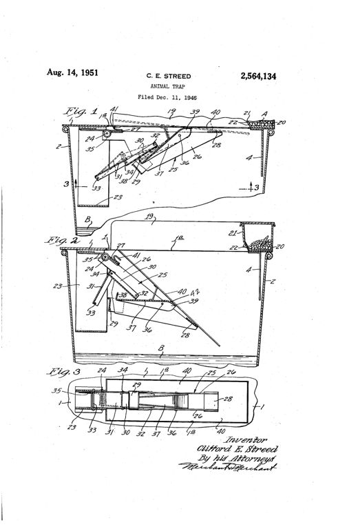
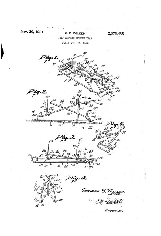
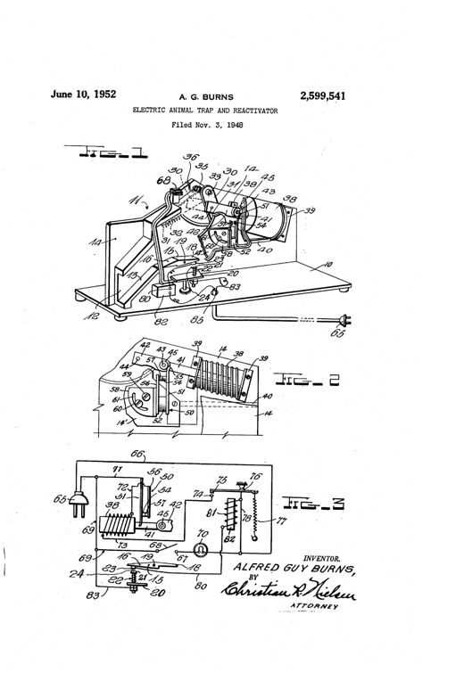
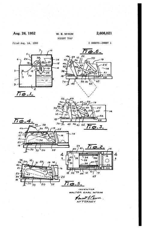
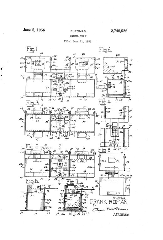
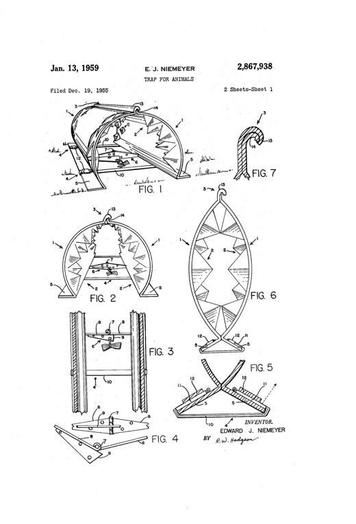
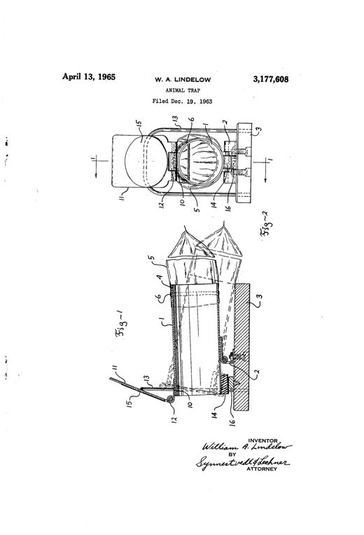
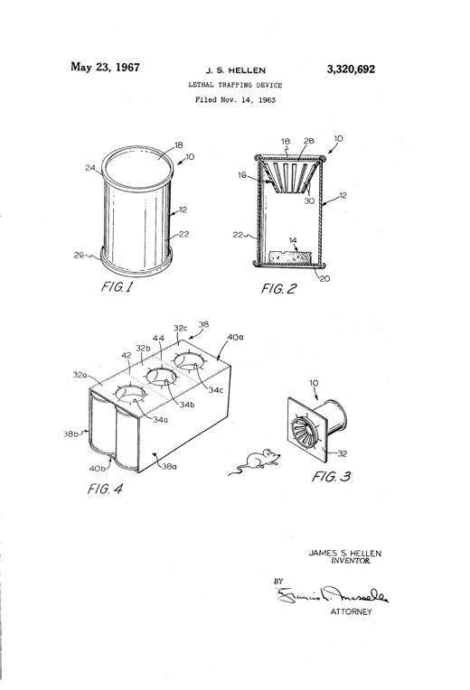
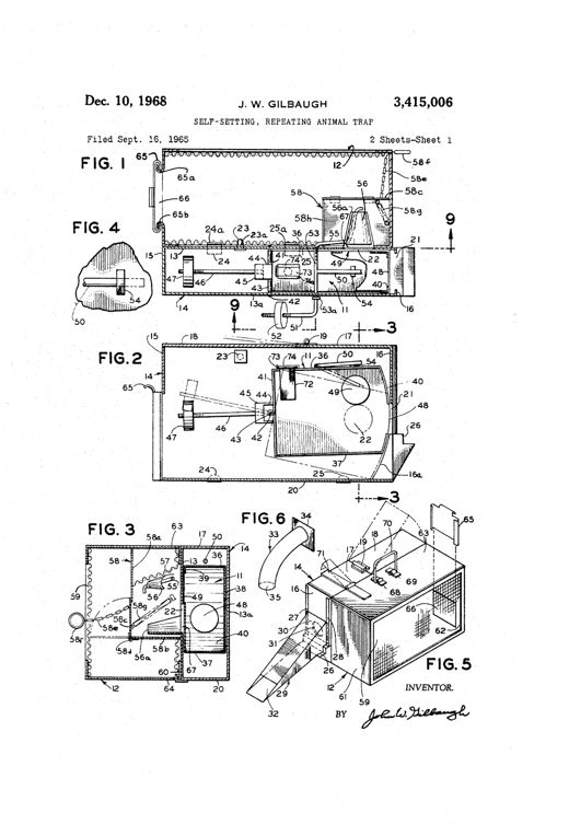
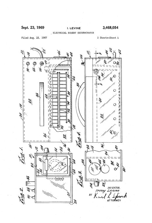
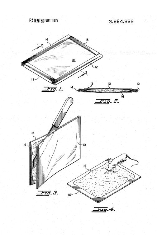
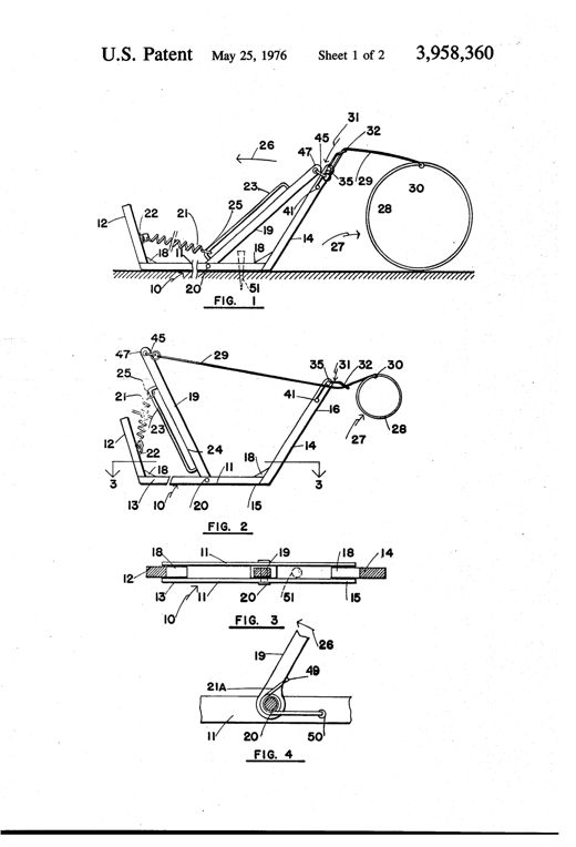
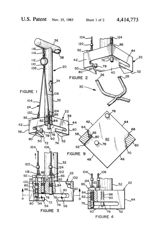
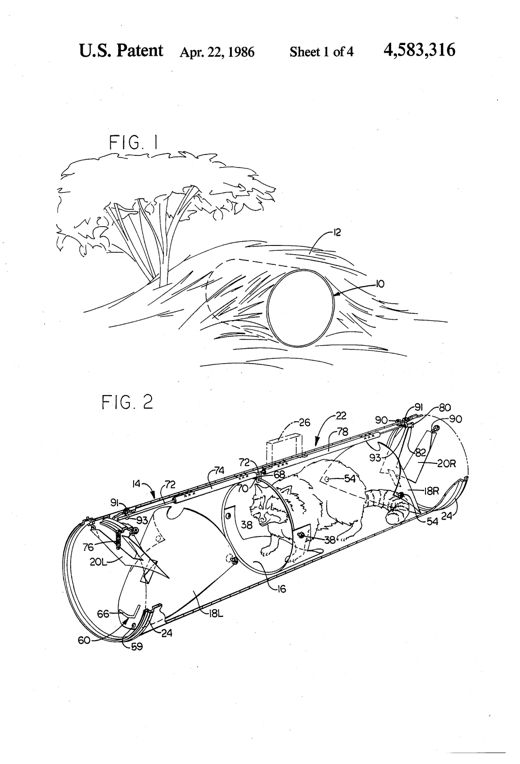
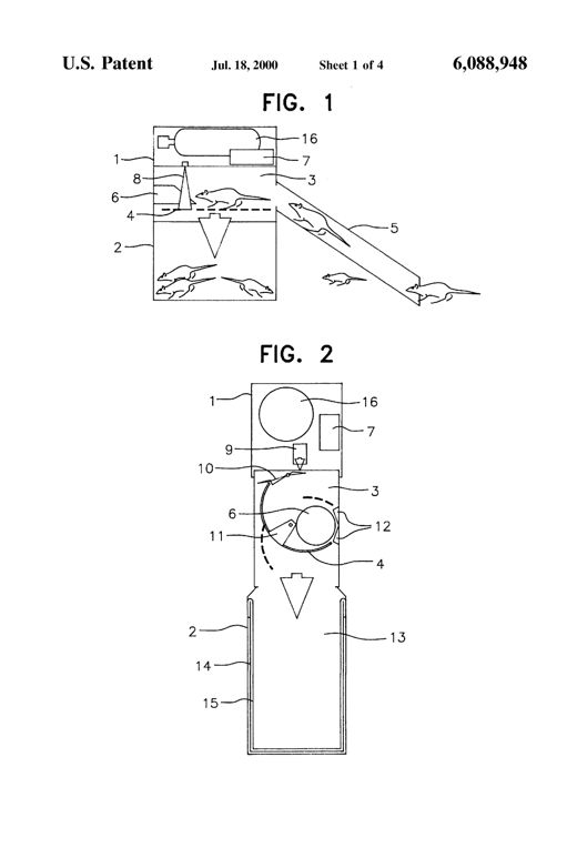
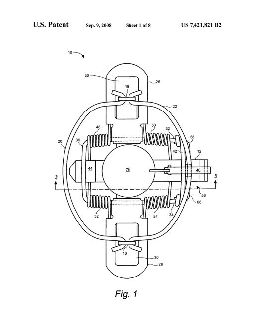
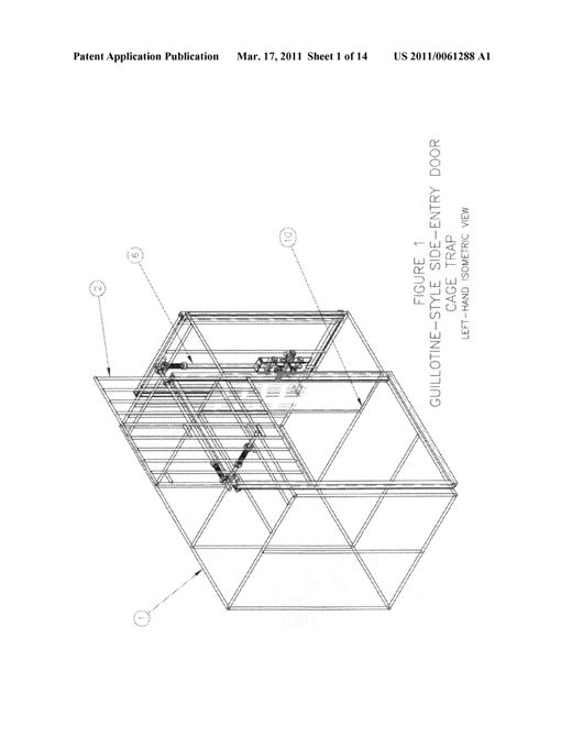
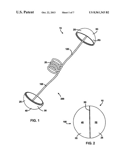
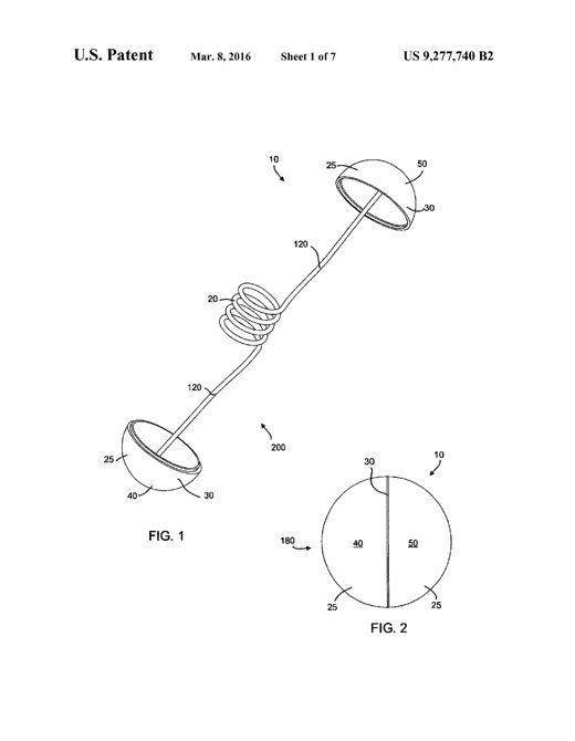
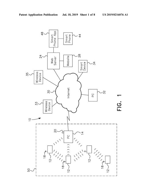
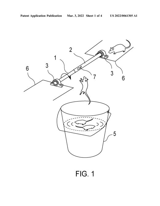
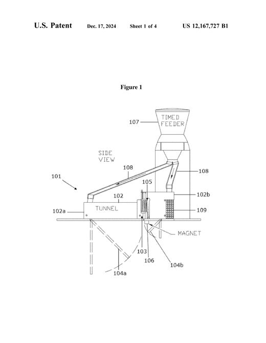
Line drawing of a wooden table-frame trap set over a forest path, with a bent sapling spring-pole overhead connected by cords to choker loops laid across slots in the tabletop, and a smaller cross-section diagram below showing the internal setting rods.IMPROVED ANIMAL-TRAPMajor B. Marshall · March 10, 1868Patent drawing of a 19th-century gopher trap showing a long frame with two parallel rods, a coiled spring at the rear, a curved guide link near the front, and a small rodent illustrated beside the trap in Figure 5.IMPROVEMENT IN ANIMAL-TRAPSJohn H. Mooney and George A. Lloyd · September 26, 1871Patent drawing of a toy-elephant-shaped mouse trap showing the animal in side profile with internal crank, spring, and lever mechanism, and a detail view of curved spring jaws at the trunk's end designed to snap shut on a mouse.ANIMAL-TRAPFrederick Glasson · December 11, 1883Patent drawing of a wooden box animal trap with a spring-loaded upper jaw held by a cord-and-pulley trigger mechanism, shown in perspective with a rat entering the open end, plus front and sectional views labeling the uprights, springs, jaws, trigger, and bait hook.ANIMAL-TRAP.Charles Richard Swan · June 28, 1887Patent drawing of an otter trap showing a plan view with two bow springs, a central bait pan and trigger mechanism, plus cross-section details of the beveled jaw shanks and cutting edges.ANIMAL-TRAP.Ethel A. Ray · December 16, 1890Patent drawing of a rectangular platform animal trap showing a wire clamping jaw with coiled springs at each end, a pivoted latch at the rear, and a trigger plate at the front, illustrated in top plan and four side sectional views labeled Fig. 1 through Fig. 5.ANIMAL-TRAP.Samuel Robinson · April 28, 1903Patent drawing of a rectangular wire cage trap showing an end view with rows of curved hooks and hanging pointed spear-hangers held by an adjustable bar, plus a detail of a single hanger and a side-section view of the trap end.TRAP.John Shepherd · October 17, 1905Patent drawing showing a steel animal trap with spring-loaded jaws and a bait pan treadle, illustrated both set upright on the ground and inverted and fastened to a tree trunk with a hooked dog fastener.ANIMAL-TRAP.David W. Solomon · September 21, 1909Patent drawing of a rectangular wire-mesh cage trap showing a perspective view, two side sectional elevations with the hinged front door open and closed, and a plan view revealing the internal bait rod, guideway, spring catches, and toothed door mechanism.ANIMAL-TRAPTheodore Vanderbilt Clapp · November 12, 1912Patent drawing of a wooden tank with hinged lid housing a wire-mesh cage trap, showing entrance tubes, a suspended bait basket contact, wire runways with hooks, and a removable mesh tray at the bottom for retrieving drowned rats.ELECTRIC RAT-EXTERMINATORJames W. M. Carmichael · September 8, 1914Patent drawing sheet showing a steel animal trap with two hinged jaws closed by a curved U-shaped spring, a pivoting trigger arm with bait pan and prongs, a trigger dog with cam surfaces, and a separate detail of a screw-in bait hook attachment.ANIMAL-TRAPJohn Campbell · August 24, 1915Patent drawing of an oval steel animal trap showing two toothed U-shaped jaws joined by a central pivot spring, with a top-view toggle setting mechanism and side views detailing the locking arm and dog components labeled with numbers 1 through 14.ANIMAL-TRAPAlbert M. Ahern · March 7, 1916Patent drawing of a jaw-type animal trap showing overlapping leaf springs, a circular jaw ring, a pivoted bait pan, a chain with ring and connecting hook, and a detent catch mechanism, illustrated in top, side, and perspective views across seven figures.ANIMAL-TRAPFerrand F. Ellis and Stephen R. Leonard · September 11, 1917Patent drawing of a rectangular base plate animal trap with two U-shaped wire jaws pivoted at opposite ends, a bait-holding trigger plate in the middle, and a coiled retracting spring connecting a crank arm to the base, shown in plan, side, and sectional views.ANIMAL-TRAPMyron A. Twitchell · September 25, 1917Patent drawing of a boxy metal rat and insect trap with flaring, ribbed outer walls, a carrying handle on top, a rotating bait spool visible through a cutaway, and hinged trap doors leading to a lower imprisoning compartment.RAT, MOUSE, AND INSECT TRAP.Louis Haege · December 3, 1918Patent drawing of a wooden box trap with an external ladder leading to a small house-like enclosure on top, and a cutaway view showing internal inclined chutes and a water reservoir at the base for drowning captured rodents.MULTIPLE TRAP.Frank Wójcik · September 28, 1920Patent drawing of a double-ended steel animal trap with two pairs of U-shaped jaws, coil springs, a central standard with pivoting latches and bait-platform triggers, and an anchoring chain, shown in plan, side, sectional, and perspective views.ANIMAL-TRAPJohn F. Arneth · August 16, 1921Patent drawing of a wooden box trap with two guide posts supporting a sliding weighted plate above an open cage, connected by cords and a pointed trigger bar to a hinged bait pan at the bottom, with a detail inset showing the adjustable weighted sleeve and notch-engaging latch.ANIMAL TRAPMichael Shutoff · January 24, 1922Patent drawing of a large dome-shaped net trap showing curved bands, U-shaped springs, hinged jaws, netting panels, and a detail of the bait-plate catch mechanism and folding curtain hardware.TRAPAugust Marengo · December 18, 1923Patent drawing of a compound animal trap showing a rectangular base with two overlapping pairs of curved spring-loaded jaws, a treadle mechanism, and a chain with attachment ring at the bottom.ANIMAL TRAPWalter A. Gibbs · August 3, 1926Line drawing of an A-frame animal trap with two long serrated arms pivoted at the top, a U-shaped spring looping below between them, a cascading set of numbered catch levers along one arm, and a trip string stretched across the front; inset figures show a front view, an enlarged catch-lever detail, and a modified spring with an adjustable rack and wedge.ANIMAL TRAPKornelius P. Kvalvik · December 13, 1927Patent drawing of an oval-framed animal trap with two hinged toothed jaws on a central shaft, a treadle and trigger mechanism inside the jaw area, and adjustable curved supporting arms allowing the trap to be mounted vertically or inverted, as shown in multiple sectional and perspective figures.ANIMAL TRAPBert Coe · September 17, 1929A rectangular metal box trap with a hinged lid and side handle, attached at an angle to a wire-screened cage that serves as a ramp and holding pen, with numbered internal parts showing a pivoted trap door, trigger lever, bait platform and one-way inlet door.ANIMAL TRAPLouis Haege · June 24, 1930Cutaway side-view patent drawing of a rounded-top animal trap body showing an internal spring-loaded yoke, bait hook, gas cartridge, plunger, and gas delivery tube positioned to release gas over an animal's head, with additional cross-section and detail views of the locking arms and cartridge assembly.ANIMAL TRAPWalter J. Lementy · May 10, 1932Patent drawing of a double-jaw animal trap showing large outer bow-spring jaws surrounding smaller inner jaws with a platform trigger and tension lever mechanism, plus detail views of the notch and catch assembly.SELECTIVE DOUBLE JAW TRAPJoseph D. Zahm · July 4, 1933Patent drawing showing a boxy animal trap housing with a toothed sliding door held open by a spring-loaded trigger crank, an internal hinged trip pan with bait spike, and coil springs along vertical guide strips that snap the door shut when the pan is depressed.ANIMAL TRAPCharles A. Kalina · July 14, 1936Technical patent drawing of a wooden rectangular mouse/rat trap base with a wire holder loop, coiled central spring, bait bar with latch, and a pivoted safety lever for raising the bait bar, shown in multiple views including hands operating the trap.MOUSE AND RAT TRAPOlin R. Booth · May 30, 1939Patent drawing of a long rectangular animal trap casing with a vertical sliding entrance door, internal treadle and spring-loaded tripping plate, a bait box with a hinged gate, and a rear execution box with hinged choking doors, shown in plan and multiple cross-sections.ANIMAL TRAPRobert C. Burnley · June 6, 1939Cross-sectional patent drawing of a house-shaped rat trap showing an upper fluid compartment with a float, a connecting rod through a tubular guide, and a lower compartment containing a movable animal chamber with a bait pan and treadle, alongside a wire mesh exit cage.TRAPJohn C. Russell · June 17, 1941Patent drawing of a rectangular wire-mesh box trap with a sloping front wall showing a hinged double door mechanism (inner and outer wing-doors) with baffle plates and latches, plus a top plan view of the internal food container and cross-sections illustrating the doors in locked and open positions.BOX-TRAP FOR CATCHING MANY ANIMALS AT ONE SETTINGHerman Mieth · March 30, 1943Mechanical line drawing of a boxy metal animal trap casing showing internal doors, pivoted sweep bars, a rotating grid shaft, stripping grid, and an electrical wiring diagram with a photoelectric cell, relay, and transformer.ANIMAL TRAPChester W. Crumrine · September 7, 1948Patent drawing of a dual animal trap showing two oval outer spring jaws (5,6) hinged at rock bars, a central smaller inner jaw pair (15,16) with a tilting bait plate (18) and trigger (21), a yoke latch (10) and latch-keeper (12), and a chain-and-ring safety device (13,14) securing the latch-keeper, all mounted on a common base plate (4) with anchoring arm (24).ANIMAL TRAPLeonard C. Johnson · September 13, 1949Patent drawing showing a jaw trap connected by chain to a plate with two zigzag springs stretched to side stakes and one long spring to a central stake, illustrated in both set (V-shaped) and released (straight-line) configurations, with a separate cross-sectional detail of a forked stake and float line marker.DROWNING ATTACHMENT FOR TRAPSGeorge Adkins · October 11, 1949Patent drawing showing three cutaway diagrams of a mechanical animal trap mounted atop a pail, with a hinged runway, toggle links, tripping lever, and a covered bait box at one end, illustrated in set and tripped positions plus a bottom plan view.ANIMAL TRAPClifford E. Streed · August 14, 1951Patent drawing of a wire-frame gopher trap showing a U-shaped base with helical springs, upward piercing arms, an overlying thumb-actuated setting lever, and a hinged trip plate, illustrated in perspective, side, and sectional views labeled Figures 1 through 5.SELF-SETTING RODENT TRAPGeorge B. Wilken · November 20, 1951Perspective cutaway drawing of a boxy electric rodent trap showing an entrance ramp leading to a tiltable platform, a solenoid-driven striker arm above it, and wiring running to an external plug, with two additional diagrams below detailing the switch mechanism and full wiring schematic.ELECTRIC ANIMAL TRAP AND REACTIVATORAlfred G. Burns · June 10, 1952Patent drawing of a rodent trap showing a casing with a pivoted tunnel, depressible runway, hinged gate, linked weight arms, and a water tank below for drowning trapped rats.RODENT TRAPWalter Earl McKim · August 26, 1952Patent drawing sheet showing eight figures of a rectangular tunnel-like animal trap housing with a hinged blade-supporting lid, weights, tilt rod, bait cup, and interchangeable blade attachments at the center and end sections, labeled with numbered reference lines.ANIMAL TRAPFrank Roman · June 5, 1956Patent drawing of a curved sheet-metal animal trap with spiked ends, shown open in perspective with an internal bait-triggered hinge, and separately closed, hinged, and stacked for storage.TRAP FOR ANIMALSEdward J. Niemeyer · January 13, 1959Patent drawing of a cylindrical tilting animal trap showing a side elevation with a disposable bag on one end and a hinged door on the other, plus a front view looking into the tube's open mouth with numbered parts including the pivot, hinge, door, magnet, and bag.ANIMAL TRAPWilliam A. Lindelow · April 13, 1965Patent drawing of a small cylindrical tin can trap with a conical finger-valve entrance at one end and poisoned bait fixed at the other, plus a six-pack cardboard carton with roll-preventing collars for multiple such cans.LETHAL TRAPPING DEVICEJames S. Hellen · May 23, 1967Patent drawings show a rectangular box trap with an internal pivoting compartment, counter-balance weights on threaded rods, a latch pin and stop mechanism, a funnel-shaped release projection, and an attached wire-mesh carrying cage with a sliding rear door.SELF-SETTING, REPEATING ANIMAL TRAPJohn W. Gilbaugh · December 10, 1968Patent drawing of a rectangular rodent exterminator box showing a floor grid, swinging baffle, magnet-held trip switch, transformer, and timer wiring diagram.ELECTRICAL RODENT EXTERMINATORIrvin Levine · September 23, 1969An exploded-style perspective drawing of a rectangular two-panel board trap with U-shaped edge brackets labeled 11-14, a center adhesive layer, a hand slicing the panels apart with a knife, and a final drawing showing a mouse stuck on the exposed adhesive-coated board.PEST CONTROL DEVICENathan Kosinsky · February 11, 1975Line drawing of a mechanical snare trap showing a triangular fixed frame with a pivoted spring-loaded arm connected by a trigger mechanism, with a snare wire loop extending to a large circular noose.SNARE TYPE ANIMAL TRAPLawrence Edward King · May 25, 1976Exploded perspective drawing of a long-handled plastic safety tool with a hollow cross-handle at top, connecting cables and a ring, leading down to a rectangular body portion fitted with retractable spring-loaded pins and triangular retaining fingers used to lock onto the open jaws of a Conibear-type animal trap.SAFETY DEVICE FOR ANIMAL TRAPThomas L. Moyers · November 15, 1983Perspective drawing of a cylindrical live-animal trap with a raccoon inside, showing the tubular casing, end doors, treadle, trigger wires, and mounting handle.ANIMAL TRAPThomas H. Holtgrefe · April 22, 1986Cutaway line drawing of a rectangular rat trap: an entrance tunnel leads a rat past a sensor into a compartment with a curved drop door beneath an overhead CO2 gas bottle and control-unit box; the door dumps the rat into a lower killing chamber holding a removable drawer.METHOD AND A DEVICE FOR TRAPPING RATS, MICE AND THE LIKEPer Rønnau · July 18, 2000Top-down technical drawing of a cross-shaped animal trap frame showing two arch-shaped jaws at top and bottom, coil springs on each side, a central circular pan labeled 70, and a U-shaped retention pin with a spring pin lock extending across the frame to a trigger mechanism.SPRING PIN LOCK FOR ANIMAL TRAPRich Butera · September 9, 2008An isometric line drawing of a rectangular wire-frame cage trap with a guillotine-style sliding door on one side, showing a spring-loaded latch and support mechanism mounted at the top corner along with connecting release rods leading toward a bait pedal.ADVANCED POWERED TRIGGER SYSTEM "SUPPORT MECHANISM" FOR CAGE AND OR CORRAL-TYPE ANIMAL TRAPSKirk Alan DeKalb · March 17, 2011Line drawing of a slingshot-style launcher firing a two-part capsule connected by a coiled wire toward a leafless tree branch, with a separate figure showing the capsule halves and coil detail.PEST CONTROL METHOD AND APPARATUSBrett Bunker Bunker · October 22, 2013A dumbbell-shaped device with two hemispherical end caps connected by a coiled wire extension, shown exploded and assembled, alongside a gun-shaped launcher and a tree with the device wrapped around a branch.PEST CONTROL METHOD AND APPARATUSBrett E. Bunker · March 8, 2016A schematic labeled FIG. 1 shows a dashed enclosure containing four boxy electronic rodent traps (12), each with a small antenna (18), sending wireless signal arcs to a central PC/base station (14) fitted with its own antenna (20); the base station links via a lightning-bolt wireless signal to a cloud labeled 'Internet' (30), which in turn connects outward to boxes labeled Wireless Device, Web Server, Website, Smart Device, PC, Smart Phone App, and Smart Phone.WIRELESS NOTIFICATION SYSTEMS AND METHODS FOR ELECTRONIC RODENT TRAPSChristopher T. Rich · July 18, 2019An isometric drawing shows a rod-like roller mounted on two pillow block bearings above a bucket of water, with two rats on angled platforms approaching the roller and another rat falling into the water below.UNIVERSAL ROLLING TRAP FOR MOUSE AND RATJakko H Yang · March 3, 2022Line drawing of a squirrel trap showing a horizontal tunnel leading to a spring-loaded kill mechanism beneath an angled chute connected to an overhead timed feeder hopper, with a hinged trap door and magnet catch below the tunnel floor.TRAPArthur Randell Bradwell · December 17, 2024