And The World Did Not Beat A Path To His Door

4,400 attempts at a solved problem

Requires the Mouse to Cooperate

Traps whose operation depends on the mouse climbing a ladder, walking a plank, entering in a specified orientation, or otherwise following instructions.
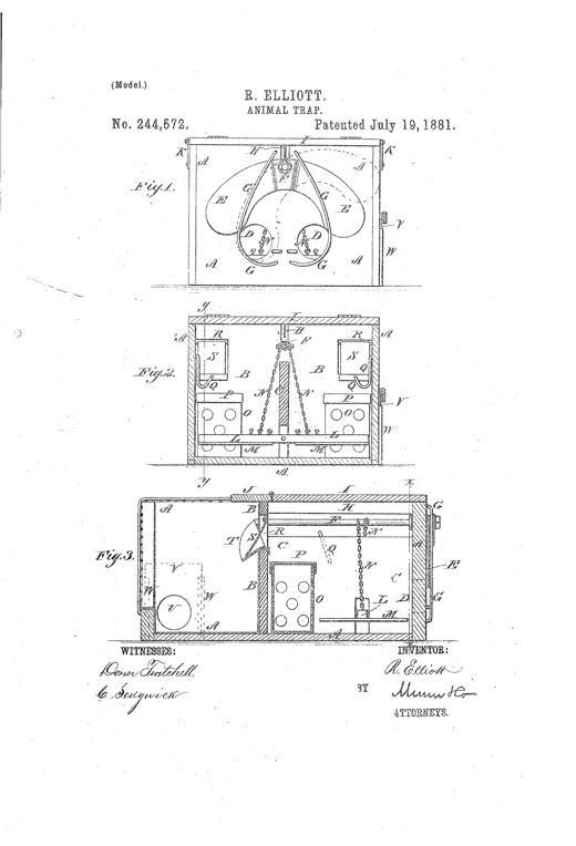
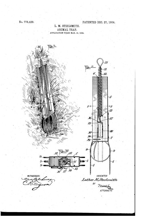
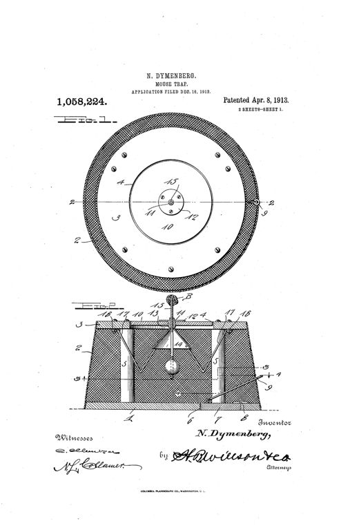
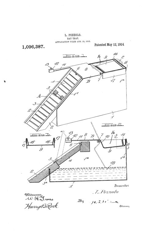
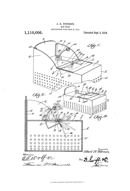
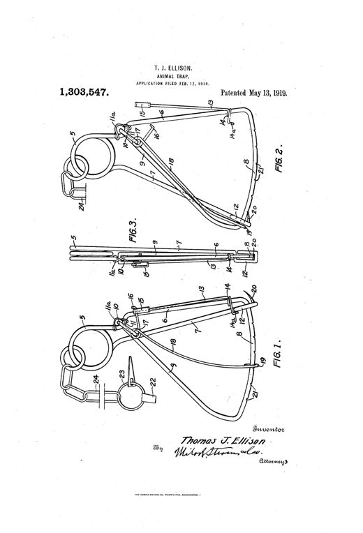
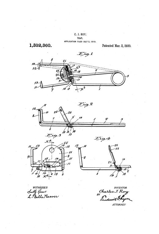
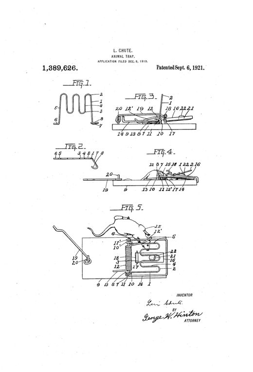
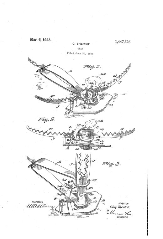
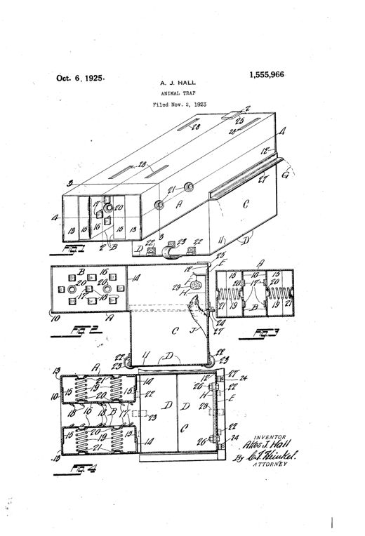
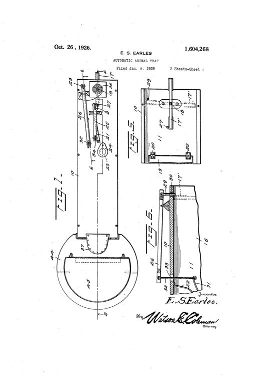
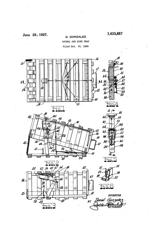
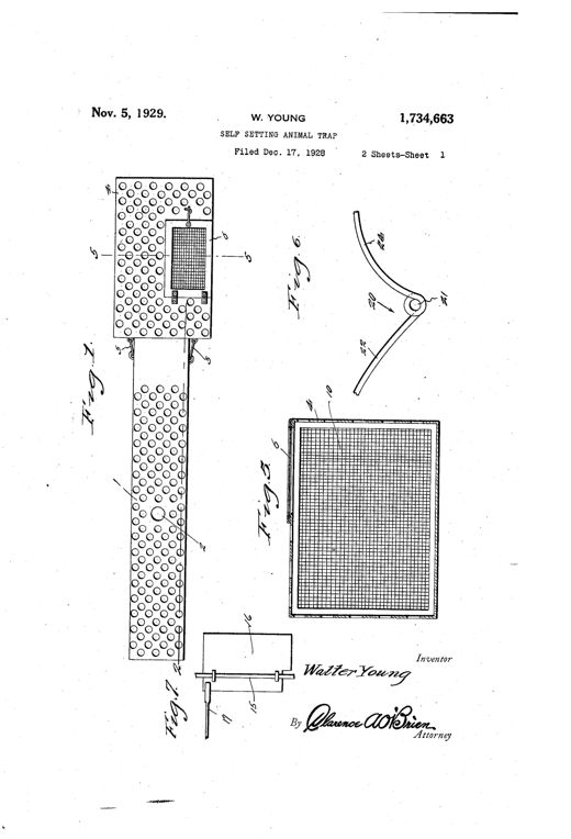
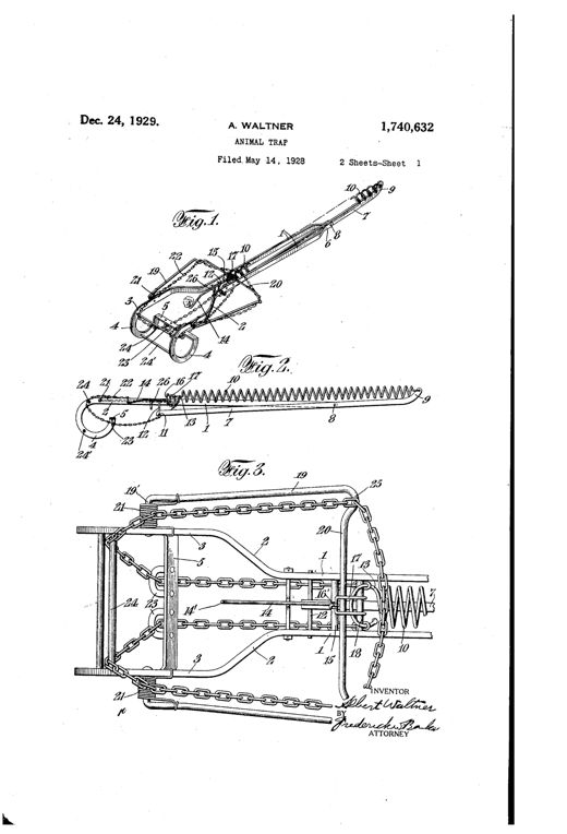
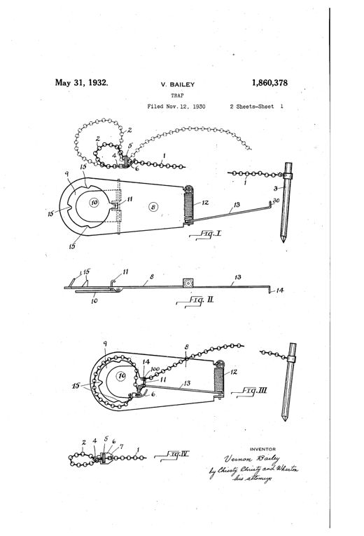
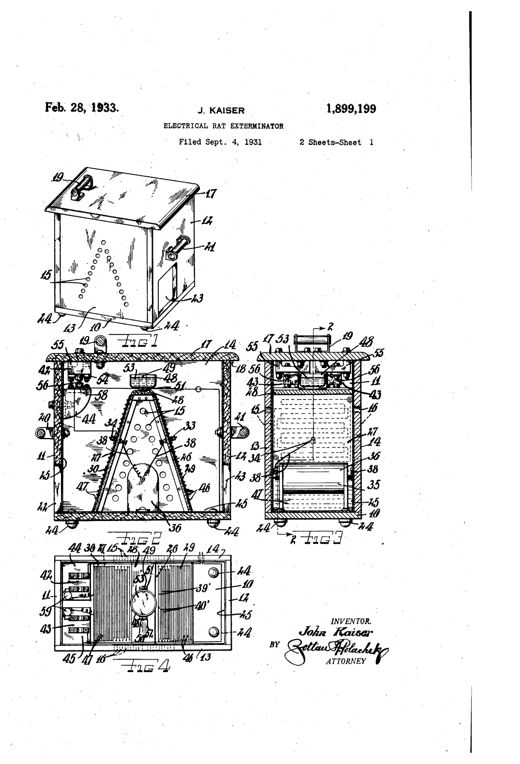
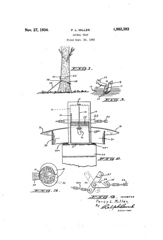
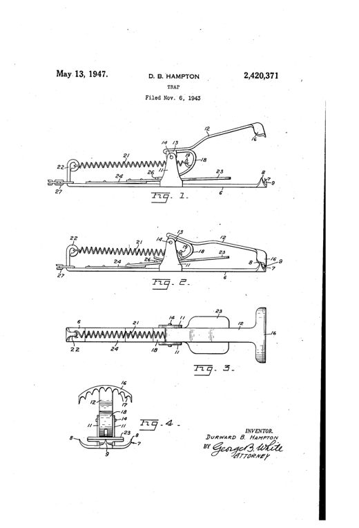
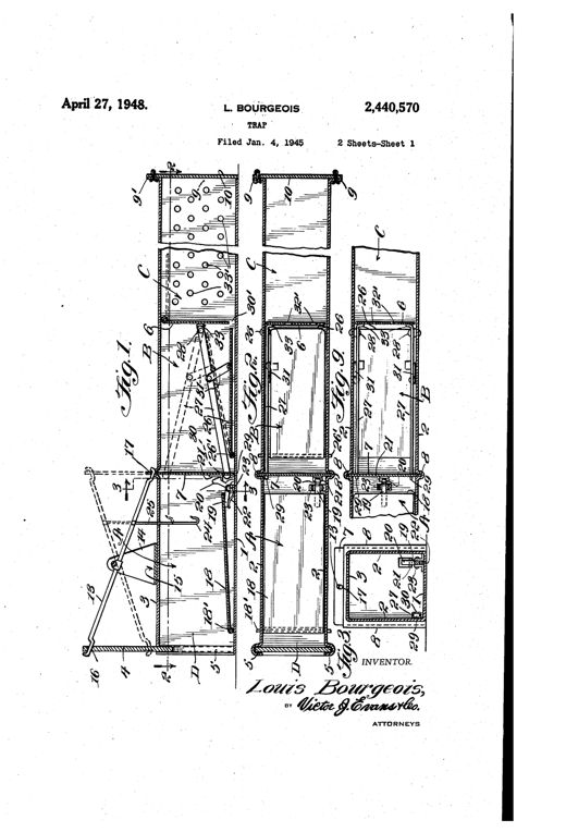
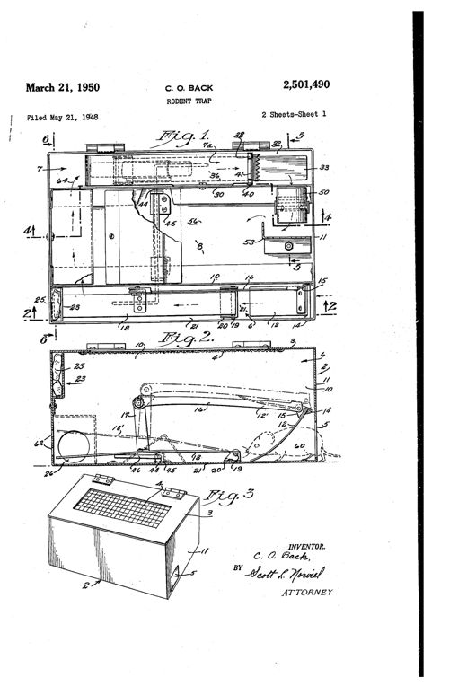
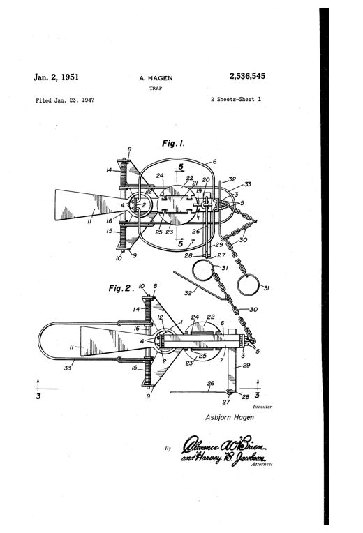
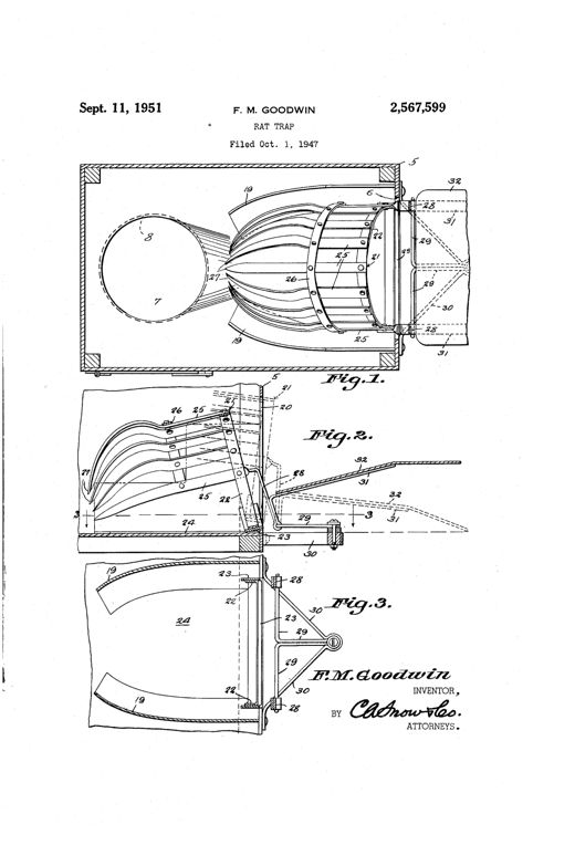
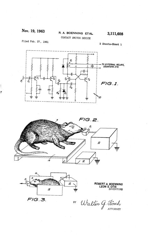
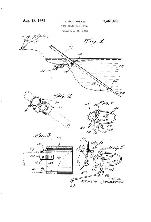
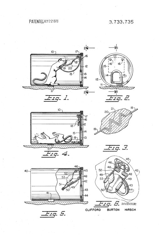
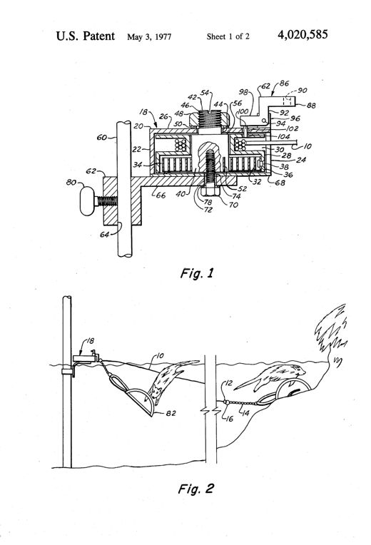
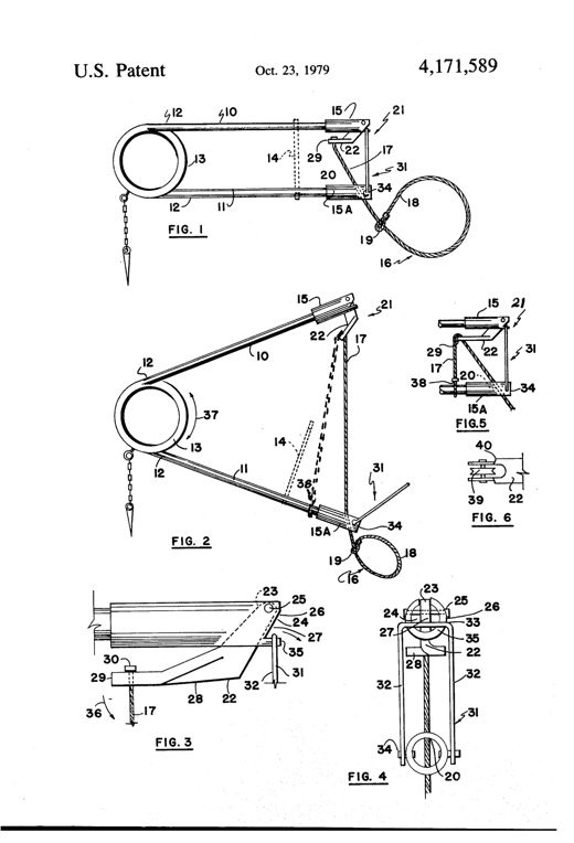
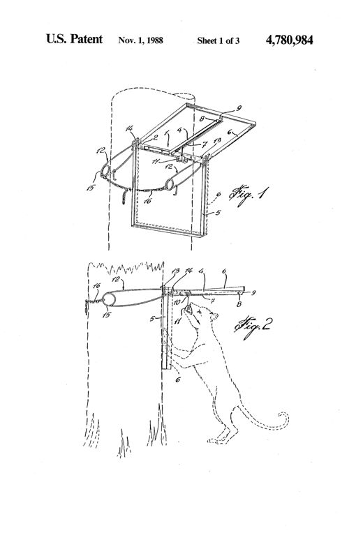
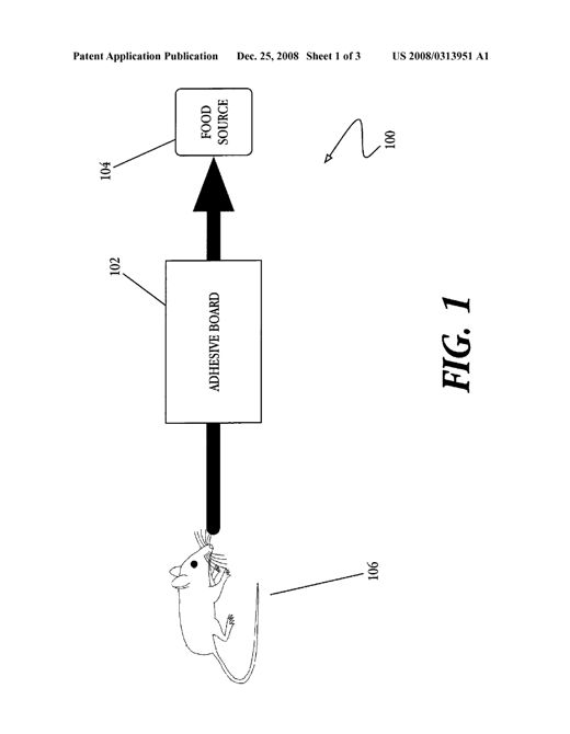
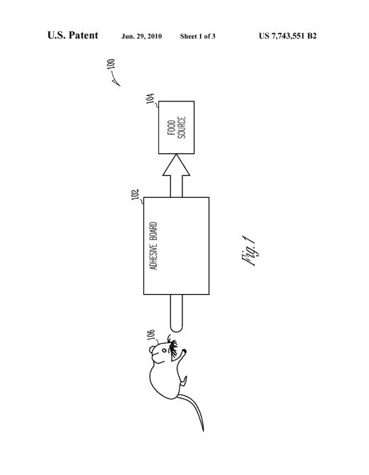
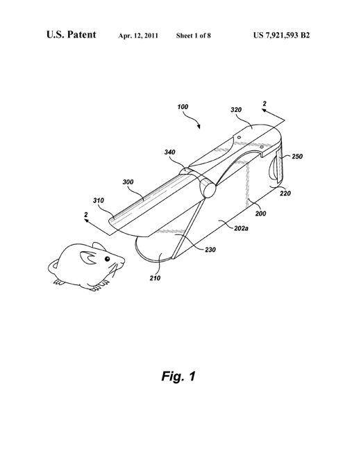
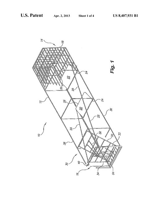
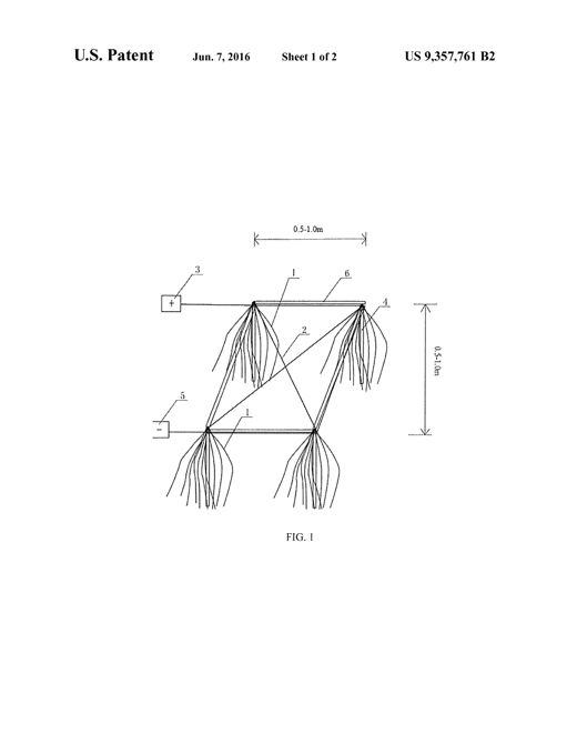
Patent drawing of a wooden box animal trap with three internal compartments, showing a front view with two circular bait-box openings and semicircular sliding plates, a sectional front view revealing the internal treadle and chain mechanism, and a sectional side view showing the drop-door and inclined spout leading to a rear holding compartment.ANIMAL-TRAPRussell Elliott · July 19, 1881Patent drawing of an elongated metal animal trap with a coiled spring inside a channel, a top pull-loop, downward puncturing prongs, ground-anchoring spikes, and two circular loops at the base sized to a burrow opening, shown both set in grassy ground and in isolated front/side views.ANIMAL-TRAPLuther M. Steelsmith · December 27, 1904Patent drawing of a round mouse cage trap showing a wire-mesh truncated cone body with a flat perforated ring top, a central tilting disk with a bait rod and hanging weight suspended over an internal cone, and a hinged door in the base for removing caught mice.MOUSE-TRAP.Noa Dymenberg · April 8, 1913Isometric and sectional patent drawings of a wooden rat trap showing an inclined slatted runway leading up to a hinged tilting door atop a water-filled tank, with a bait trough, counterweight arm, and stop flanges labeled by numbers.RAT-TRAPLoui Pezzolo · May 12, 1914Patent drawing of a perforated metal box rat trap with a sliding door on one end and a hinged, coiled-wire bait arm and tilting platform mechanism on the top, shown in three perspective and sectional views.RAT-TRAP.Albert R. Peterson · September 8, 1914Patent drawing showing a wire loop trap with two spring coils, a triangular loop arm assembly with numbered parts, a trigger bar, and an attached chain with anchoring stake, illustrated in set (Fig. 1), sprung (Fig. 2), and side (Fig. 3) views.ANIMAL-TRAP.Thomas J. Ellison · May 13, 1919Patent drawing of a gopher trap with two crossing spring-steel arms bent into jaws with sharp points, joined by a coiled spring at the rear, and a semicircular trigger plate with a light-admitting hole mounted on the cross bar to release the jaws.TRAP.Charles J. Roy · March 2, 1920Patent drawing showing a bent-wire grid shield (Figs. 1-2) that attaches via hinges and a crank to a conventional snap-style animal trap, illustrated set (Fig. 3) and sprung with a rat caught between the jaw and body (Figs. 4-5).ANIMAL-TRAPLevi Chute · September 6, 1921Line drawing of an antique steel trap with two long serrated arcuate jaws mounted on a central post over a hexagonal base plate, connected to a bent bow-spring and a baited trigger latch mechanism, shown set in Fig. 1 and 2 and sprung shut in Fig. 3.TRAPClay Theriot · March 6, 1923Exploded perspective and sectional drawings of a rectangular sheet-metal animal trap showing an entrance chamber with spring-loaded toothed walls, a central bait passage, hinged trap doors at the bottom, and a rear door fitted with a mirror, all labeled with numbered reference parts.ANIMAL TRAPAkos J. Hall · October 6, 1925Patent drawing of an elongated rectangular animal trap casing divided into two compartments by a partition, showing a pivoted swinging door, a spring-loaded treadle platform, a slanted one-way grating passageway, control levers and springs on top of the casing, and a rear storage compartment with a self-restoring cover platform.AUTOMATIC ANIMAL TRAPElisha S. Earles · October 26, 1926Patent drawing sheet showing a rectangular wooden slatted cage trap with hinged top, a bait container box on one end, and detailed mechanical views of the spring-loaded latch, catch, and locking hooks that hold the cage open and snap it shut.ANIMAL AND BIRD TRAPDaniel Gonzalez · June 28, 1927Patent drawing of an elongated perforated metal box trap with a hinged screened door at one end, an internal tilting platform and trigger arm, a rear resetting treadle, and a V-shaped wire linkage connecting the treadle to the door and platform mechanism.SELF SETTING ANIMAL TRAPWalter Young · November 5, 1929Patent drawing of a wire-frame animal trap showing a long lever bar, a helical spring, a yoke with chains for throwing a chain loop over an animal's neck, and a bait hook mechanism with locking U-shaped support.ANIMAL TRAPAlbert Waltner · December 24, 1929Patent drawing of a leg-hold noose trap showing a hinged treadle pan connected to a coiled spring wire arm that throws a chain noose upward, with a ground stake and detailed views of the chain's locking terminal link.TRAPVernon Bailey · May 31, 1932An angled line drawing of a wooden hinged-top box with a slanted lid, side handles, small entry holes arranged in triangular patterns, and internal cutaway views showing two angled electrified wire grids leading up to a pivoted oil bait cup.ELECTRICAL RAT EXTERMINATORJohn Kaiser · February 28, 1933Patent drawing showing a spring-loaded rectangular trap frame strapped vertically to a tree trunk with angled wing guards, a hinged bait hook trigger, a downward runway, and a chain tightening lever mechanism.ANIMAL TRAPPercy Lorne Miller · November 27, 1934Technical patent drawing of a gopher trap showing a base with fixed toothed cross-bar jaw, a pivoting lever with a curved toothed jaw and coil spring, and a spring-loaded treadle between bearing brackets, illustrated in open, closed, top, and end views.TRAPDurward B. Hampton · May 13, 1947Patent drawing of an elongated rectangular tubular animal trap box showing a sliding front door, internal hinged and sliding partitions forming successive chambers A, B, and C, an oscillating overhead bar linking the door and partitions, pivoted floor plates acting as treadles, and a perspective view of the trap attached to a larger perforated jail box with a sliding lid and screened vent.TRAPLouis Bourgeois · April 27, 1948Patent drawing of a rectangular metal rodent trap case showing internal partitions forming an entrance runway, transverse passageway, reset runway, and central pen, with hinged floor plates, cranks, links, a rolling-ball positioning tube, and non-return gates labeled with numbered reference lines.RODENT TRAPClifford Osmon Back · March 21, 1950Patent drawing of a Y-shaped animal trap showing spring-loaded U-shaped jaws, a hinged treadle pan, locking pin mechanism, and a pivoting guard beneath the jaws, connected to a chain with rings for tethering.TRAPAsbjorn Hagen · January 2, 1951Patent drawing showing a boxlike rat trap housing in cross-section with a curved finger guard closure at the entrance, an external treadle bar, and a rear outlet flange leading to a bait receptacle, with three figures labeled Fig. 1, Fig. 2, and Fig. 3 and the inventor's signature at bottom.RAT TRAPFrank M. Goodwin · September 11, 1951Patent drawing showing an electronic circuit schematic with transistors and a relay, alongside an illustration of a rat touching a metal contact plate connected to a boxed circuit labeled '10' on a grounded metal floor.CONTACT SWITCH DEVICERobert A. Boenning · November 19, 1963Patent drawing showing a metal ring with sharp prongs sliding down a sharpened pole driven into a pond, connected by chain to an animal trap at the water's edge, with additional detail views of the ring, a leaded weight version, and a toothed sleeve version.TRAP-CHAIN LOCK RINGFrancis Boudreau · August 19, 1969Cutaway drawing of a cylindrical can-shaped trap showing a rat reaching through a small opening to bite bait attached to a spring-loaded door, with numbered parts labeling the container, door, links, and rivets.ANIMAL TRAPClifford Burton Hirsch · May 22, 1973Cutaway drawing of a cylindrical spring-motor housing mounted on a stake, containing a coiled spring and spool wound with cable, with a latch arm above; a second figure shows the housing staked in water with a cable running to a jaw trap holding a small animal being pulled underwater.ANIMAL TRAPPING APPARATUSMelvin D. Benschoter · May 3, 1977Line drawing of a spring-armed animal trap showing two parallel arms joined by a coiled spring, a trigger mechanism with pivoting lever and U-shaped bail at the opposite end, and a wire snare loop with sliding ring extending from the trigger assembly.SNARE TYPE ANIMAL TRAPKenneth G. Brownlie · October 23, 1979Perspective line drawing of a rectangular wire-frame animal trap mounted vertically against a tree trunk, showing a fixed V-shaped jaw, a hinged U-shaped movable jaw, a bait-triggered detent lever, and coiled spring wires with a chain wrapping around the tree to hold the trap in place.ANIMAL TRAPPaul Courty · November 1, 1988A line drawing shows a mouse (106) approaching a rectangular block labeled 'ADHESIVE BOARD' (102), with a bold arrow pointing onward to a rounded box labeled 'FOOD SOURCE' (104), illustrating the rodent's travel path across the glue trap toward its food.PEST CONTROL APPARATUS AND SYSTEMSDennis Siebert · December 25, 2008Exploded line drawing of a rectangular enclosure with two side panels and a top piece containing a slot for a transparent barrier panel, shown alongside a semi-elliptical variant and a diagram of a mouse approaching an adhesive board leading to a food source.PEST CONTROL APPARATUS AND SYSTEMSDennis Siebert · June 29, 2010Line drawing of a wedge-shaped rodent trap housing with a pivoting snare bar mounted near the entrance, shown with a rat approaching and, in another view, caught partially inside the loop mechanism.RODENT TRAP HAVING A SNAREPeter J. Everett · April 12, 2011Perspective line drawing of an elongated rectangular mesh cage trap with a hinged door frame at one end, internal diagonal braces, and pressure-plate linkage rods running the length of the cage.TRAPPING METHOD AND APPARATUSJohn Humphrey · April 2, 2013Line drawing of four bushy root-like fish nests arranged in a rectangle, wired diagonally to a positive terminal box and a negative terminal box, with dimension arrows marking 0.5-1.0 meter spacing between nests.VISCOUS FISH EGG KILLING DEVICEXiaotao Shi · June 7, 2016